Understanding Plant 3D Isometrics
What are Plant 3D Isometrics?
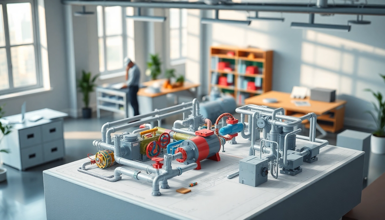
Isometric drawings are a crucial aspect of engineering design, particularly in the context of Plant 3D isometrics. They represent three-dimensional objects in a two-dimensional format, enabling detailed visualization of how various components in a plant layout interconnect. All elements within a plant are constructed and represented in a way that preserves their dimensions and spatial relationships, thus providing an accurate model for construction and maintenance.
Importance of Isometrics in Design
Understanding the importance of isometrics is paramount for engineering projects. They facilitate clear communication between engineers, project managers, and other stakeholders. By conveying complex relationships among components in a simplified manner, isometrics help in reducing misunderstandings and errors that could arise during construction. Furthermore, isometric drawings supplement traditional plans by focusing on critical elements like pipe sizes, lengths, fittings, and supports, which are essential for ensuring safety and efficiency.
Key Components of an Isometric Drawing
A well-designed isometric drawing typically includes several key components:
- Piping: Detailed representation of pipes with information regarding diameters and materials.
- Fittings and Valves: Clearly marked fittings and valve positions to indicate operational requirements.
- Ducts and Vessels: Integration of ducts and auxiliary vessels as necessary for comprehensive representation.
- Dimensions and Notes: Inclusion of relevant dimensions and engineering notes to clarify design intent.
Configuring Plant 3D Isometrics
Setting Up Your Project for Isometric Drawings
Configuring isometric drawings effectively starts with proper project setup in Plant 3D. This includes defining the project structure and ensuring the appropriate templates are used. Selecting the correct units of measurement and ensuring consistency across design elements are critical. Organizing the project files and establishing a logical hierarchy will facilitate smoother access to isometric drawing resources later in the process.
Adjusting Isometric Styles and Templates
Isometric styles can be customized in Plant 3D to align with project requirements. Users can adjust template designs to enhance clarity and ensure compliance with company standards. This includes modifying drawing scales, line weights, and symbols used in representation. Templates should be carefully selected to create professional, industry-standard outputs that can be easily interpreted by engineers and contractors.
Common Configuration Errors and Solutions
While configuring isometric settings, errors can lead to significant setbacks. Common configuration mistakes include incorrect unit settings, misaligned template parameters, and failure to establish proper styles. To rectify these errors, it's advisable to conduct thorough checks and regularly consult best practices. Utilizing predefined templates and tools provided within Plant 3D will also help minimize configuration issues.
Extracting Isometric Drawings
Step-by-Step Process for Isometric Extraction
The extraction process for creating isometric drawings involves several straightforward steps. Initially, users must select a piping model configured in Plant 3D. Following selection, the extraction options within the software should be accessed, where users can define parameters such as scale and view angles. Upon finalizing preferences, users execute the extraction command to generate the corresponding isometric drawing.
Best Practices for Effective Extraction
To ensure effective extraction of isometric drawings, adhering to best practices is vital. Regular training sessions for engineers should be conducted to ensure they are familiar with the latest software updates and extraction methodologies. Additionally, it is beneficial to have a standardized naming convention for files to avoid confusion. Always verify the resulting drawings against original project specifications to guarantee accuracy.
Common Challenges and Troubleshooting
During the extraction process, users may encounter challenges such as missing components or inaccuracies in dimensions. These issues can arise from improper initial configurations or updates in the model after the initial setup. Troubleshooting often involves revisiting the model settings and ensuring all components are correctly defined prior to extraction. Engaging in a systematic review process will also help identify areas needing improvement.
Enhancing Your Isometric Visuals
Tips for Customizing Isometric Symbols
Customizing symbols on isometric drawings can enhance their clarity and provide more contextual information. Users can create bespoke symbols that reflect specific engineering standards or functionalities required in their projects. Regular reviews and updates of these symbols should be integrated into organizational workflow to keep up with evolving standards.
Applying Color Schemes for Clarity
Utilizing color schemes effectively can significantly boost the interpretability of isometric drawings. Different colors can be assigned to indicate various materials, pressures, or operational states. This visual differentiation eases understanding for stakeholders reviewing the drawings and can prevent operational mistakes due to misinterpretation.
Integrating Annotations for Better Understanding
Annotations play a critical role in enhancing the comprehensibility of isometric drawings. Users should integrate relevant notes, dimensions, and design intentions directly within the isometric view. Annotations should be concise yet informative, thus providing vital context that may not be immediately visible from the drawing itself.
Analyzing Performance and Efficiency
Metrics for Evaluating Isometric Drawings
Measuring the effectiveness of isometric drawings can be accomplished through a variety of metrics. Key performance indicators can include the accuracy of dimensions, clarity of information presented, and stakeholder feedback. Regular assessments against these metrics will inform necessary adjustments to improve overall design accuracy and communication efficiency.
Feedback for Continuous Improvement
Continuous improvement is essential in any design process. Regularly seeking feedback from engineers and construction teams regarding the usability of isometric drawings can help identify recurring issues. Establishing a feedback loop and acting on it will strongly enhance future project outcomes.
Case Studies on Improved Pipeline Designs
Several case studies illustrate the efficiency gains achieved through the adoption of well-structured isometric drawings. Projects that implemented standardized isometric conventions resulted in reduced design cycles and fewer construction errors. Highlighting these successes encourages teams to continue refining their design approaches, leading to better results for future endeavors.
FAQs about Plant 3D Isometrics
What are Plant 3D isometrics used for?
Plant 3D isometrics are used for creating two-dimensional representations of three-dimensional piping and plant layouts to facilitate understanding and construction.
How can I customize my isometric symbols?
You can customize isometric symbols in Plant 3D by using the settings menu to create or modify existing symbols, ensuring they meet your project standards.
What common errors occur during isometric extraction?
Common errors during extraction include missing components, incorrect dimensions, and configuration mismatches resulting from improper project setup.
How can I improve the efficiency of my isometric drawings?
Efficiency can be improved by adopting standardized templates, training staff, and regularly assessing drawing clarity and accuracy against project requirements.
Are annotations necessary in isometric drawings?
Yes, annotations are crucial in isometric drawings as they provide context and details which enhance understanding and communication across project teams.