Understanding Plant 3D Isometrics
What Are Plant 3D Isometrics?
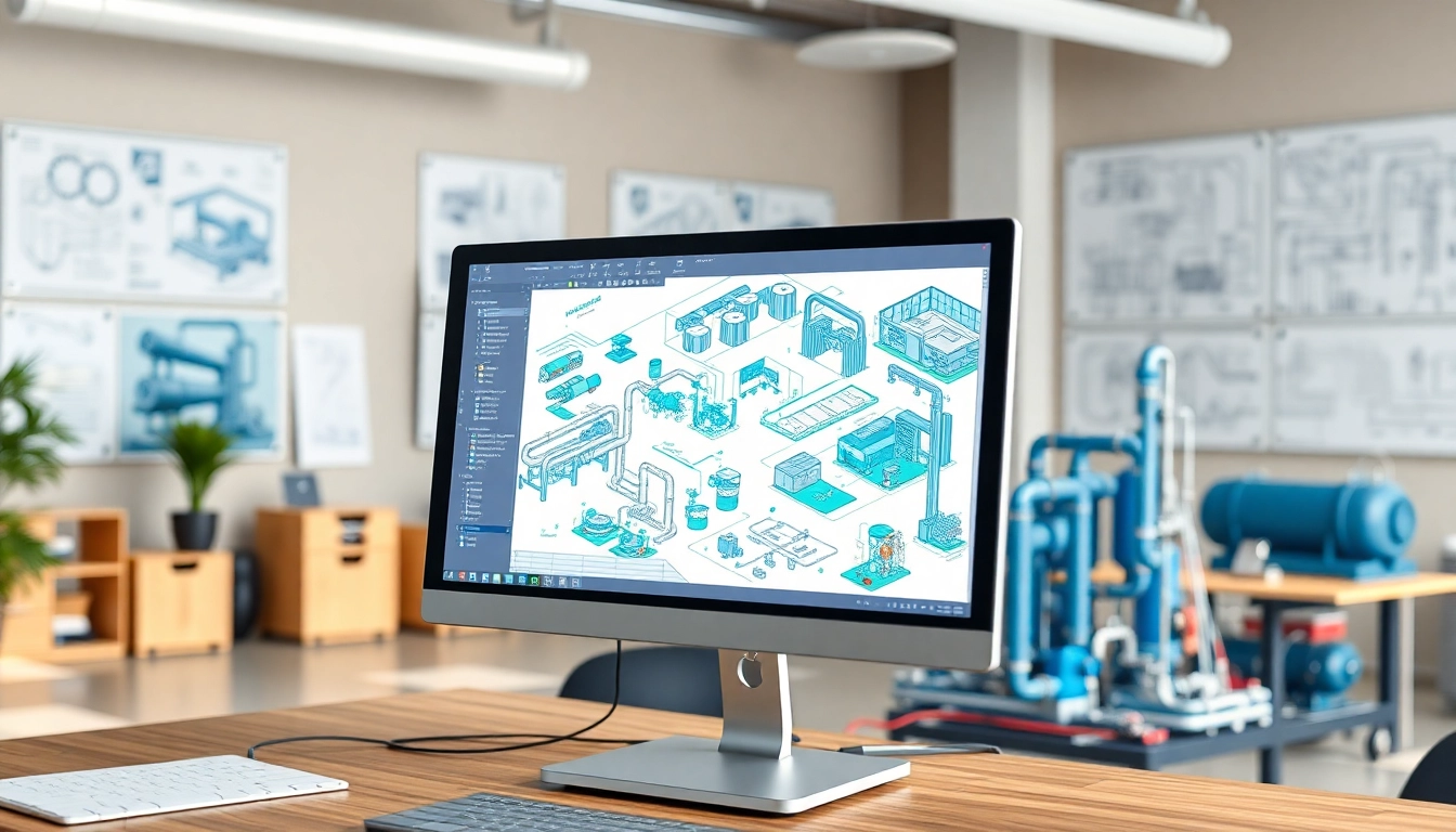
Plant 3D isometrics refer to a streamlined method of representing three-dimensional plant designs in a two-dimensional format. They serve as a crucial tool for project engineers and designers in effectively visualizing the arrangement and networking of piping systems in engineering projects. By leveraging Plant 3D isometrics, professionals can obtain detailed insights into both spatial layouts and operational workflows within plant designs. Essentially, they capture important design information in a concise format, facilitating easier comprehension and communication among project stakeholders.
Importance of Isometrics in Design
The use of isometric drawings is not just a matter of preference; it is a necessity in modern engineering design. Isometrics assist in conveying complex ideas and layouts clearly and efficiently, which can help reduce misinterpretations that might arise from reading standard architectural drawings. They are also invaluable when planning installations, as they provide a clear perspective on how components fit within the space available, ensuring that designers can anticipate and navigate potential conflicts.
Core Components of Plant 3D Isometrics
Several critical components make up Plant 3D isometrics:
- Piping Systems: The backbone of any plant layout, accurately depicted to show flow direction and connections.
- Valves: Inclusion of various types of valves is necessary to illustrate control points within the system.
- Equipment: Major equipment, such as pumps and tanks, must be represented to capture their specific locations and relationships with piping.
- Annotations: Important notes, including dimensions and specifications that provide context to the drawing.
Setting Up Your Environment for Plant 3D Isometrics
Necessary Software and Tools
Successfully navigating the realm of Plant 3D isometrics necessitates a robust suite of software and tools. It's essential for professionals to employ tools like AutoCAD Plant 3D, which offers dedicated features for creating isometric drawings. Other supporting tools can include data management systems and project collaboration software like BIM 360 that help to streamline workflow and ensure teamwork remains efficient.
Configuring Your Workspace
Setting up your workspace adequately is pivotal for optimizing productivity. Organize your software interface by customizing tool palettes and developing a standardized template for isometric drawings. This allows for ease of access to frequently used functions and ensures consistency across all drawings, thereby minimizing errors and saving time.
Best Practices for Organization
Adopting best practices in organization goes beyond the immediate workspace. Establish a structured folder system for project files, including subfolders for isometrics, specifications, and legacies of former projects. Consistency in file naming, version control, and documentation practices is also essential for maintaining clarity throughout the project lifecycle.
Creating Isometric Drawings
Step-by-Step Guide to Drawing
Creating an isometric drawing can feel daunting without a structured approach. Here’s a step-by-step guide:
- Set Up the Drawing: Start a new project using the relevant template that includes all necessary layers and styles.
- Insert Components: Begin adding your components like pipes, valves, and equipment to the drawing. Use the proper dimension settings to ensure accuracy.
- Connect Elements: Use the appropriate drawing commands to create connections between the elements in the drawing.
- Finalize Annotations: After the main components are in place, finalize your annotations, including detailed labels and dimensions.
- Review and Revise: Make sure to review the drawing for any inaccuracies before finalizing it for presentations.
Common Challenges and Solutions
While creating isometric drawings, several challenges may arise. Here are common issues and their respective solutions:
- Misalignment: Ensure to frequently check the snap settings to avoid unintentional misalignment during drawing.
- Complexity in Display: Utilize layers effectively to manage overlapping elements and avoid a cluttered appearance.
- Time Consumption: Streamline processes by creating macros for repetitive tasks and employing shortcuts for speed.
Tips for Accuracy in Isometric Drawings
Accuracy is paramount in creating effective isometric drawings. Here are some expert tips:
- Regular Checks: Regularly check existing drawings for compatibility with new components to avoid conflicts.
- Utilize Reference Drawings: Use existing isometric drawings as references to maintain consistent designs.
- Collaborate Effectively: Foster open communication among team members to catch potential errors early in the design process.
Advanced Techniques for Plant 3D Isometrics
Customization of Isometric Styles
Customization allows for flexibility in Plant 3D isometrics. By modifying isometric styles, designers can cater to project-specific requirements. Familiarizing yourself with customizing templates and styles will help standardize how drawings are presented within your organization, allowing for better coherence among various projects.
Integrating Automatic Annotations
Automatic annotation features save significant time and ensure uniformity across isometric drawings. By creating a library of annotations that automatically populates relevant fields, such as alignment details and material specifications, you can streamline many mundane tasks, freeing design teams to focus on more innovative aspects of their projects.
Utilizing External References Effectively
To maintain workflow efficiency, it’s advantageous to effectively manage external references within Plant 3D. Leverage them to link drawings and maintain coherence between multiple isometric diagrams. This helps ensure that any updates made in a parent drawing are reflected in all child drawings automatically, minimizing the risk of outdated information spreading across project documents.
Measuring Success: Key Performance Metrics
Assessing Efficiency Through Isometric Drawings
Evaluating effectiveness in isometric drawing production can be done by tracking project timelines and the amount of rework required. Compare these metrics against benchmarks or historical data from previous projects to identify areas for improvement.
Feedback Loops and Continuous Improvement
Establishing a feedback mechanism ensures continuous improvement within the drawing process. Utilize team reviews for isometric drafts to gather insights into areas that could be improved, enhancing both design quality and accuracy over time.
Real-World Case Studies: Success Stories
Numerous projects have benefitted tremendously from effective use of Plant 3D isometrics. Companies have reported improved accuracy in project execution and reduced installation times due to better-prepared isometric drawings, leading to efficient workflows and enhanced client satisfaction. Documenting these success stories can offer valuable lessons for ongoing and future projects.
FAQs About Plant 3D Isometrics
What is the primary benefit of using isometric drawings?
The primary benefit is clear visualization of 3D components in 2D space, facilitating better understanding and communication among stakeholders.
Are there specific tools needed for creating plant 3D isometrics?
Yes, software like AutoCAD Plant 3D is essential for creating detailed and accurate isometric drawings efficiently.
How can I ensure accuracy in isometric drawings?
Regular checks, utilizing templates, and maintaining collaborative communication can significantly enhance accuracy in drawings.
What common challenges arise in isometric drawing creation?
Challenges include alignment issues, complexity in displays, and time consumption. Addressing these with best practices is crucial.
How can automatic annotations improve efficiency?
Automatic annotations save time on repetitious tasks and ensure consistency across isometric drawings by pre-filling required information.